DIGITAL FABRICATION METHODS - ABB ROBOT ARM / CLAY PRINTING ENDEFFECTOR / GRASSHOPPER
Anatomy of a Machine:
Shape “Blobs & Lines”
Exploring Clay 3D Printing Through Viscosity, Speed, and Time
For the Shape exercise within Anatomy of the Machine, we worked with clay as a material, specifically focusing on robotic 3D printing using clay extrusion. The objective was to understand how material behavior, robotic parameters, and geometry interact, and how form emerges from the machine–material relationship.
Material Calibration: Clay Viscosity
We began with manual robotic tests to calibrate the viscosity of the clay and understand its behavior during extrusion.
The first mixture consisted of 2 kg of clay with 15 mm of water. This formula resulted in a very dry material; however, it was useful for initial manual handling tests with the robot. At this stage, we focused on basic movement, extrusion control, and waiting time between actions. It was during these early tests that the first notion of the “blob” emerged as a recognizable unit of form.
We then tested a second mixture with 1.5 kg of clay and 50 mm of water, achieving a higher viscosity and significantly better extrusion behavior. This mixture allowed us to increase printing speed and obtain more consistent results.
Anatomy of a Line: Speed vs. Height
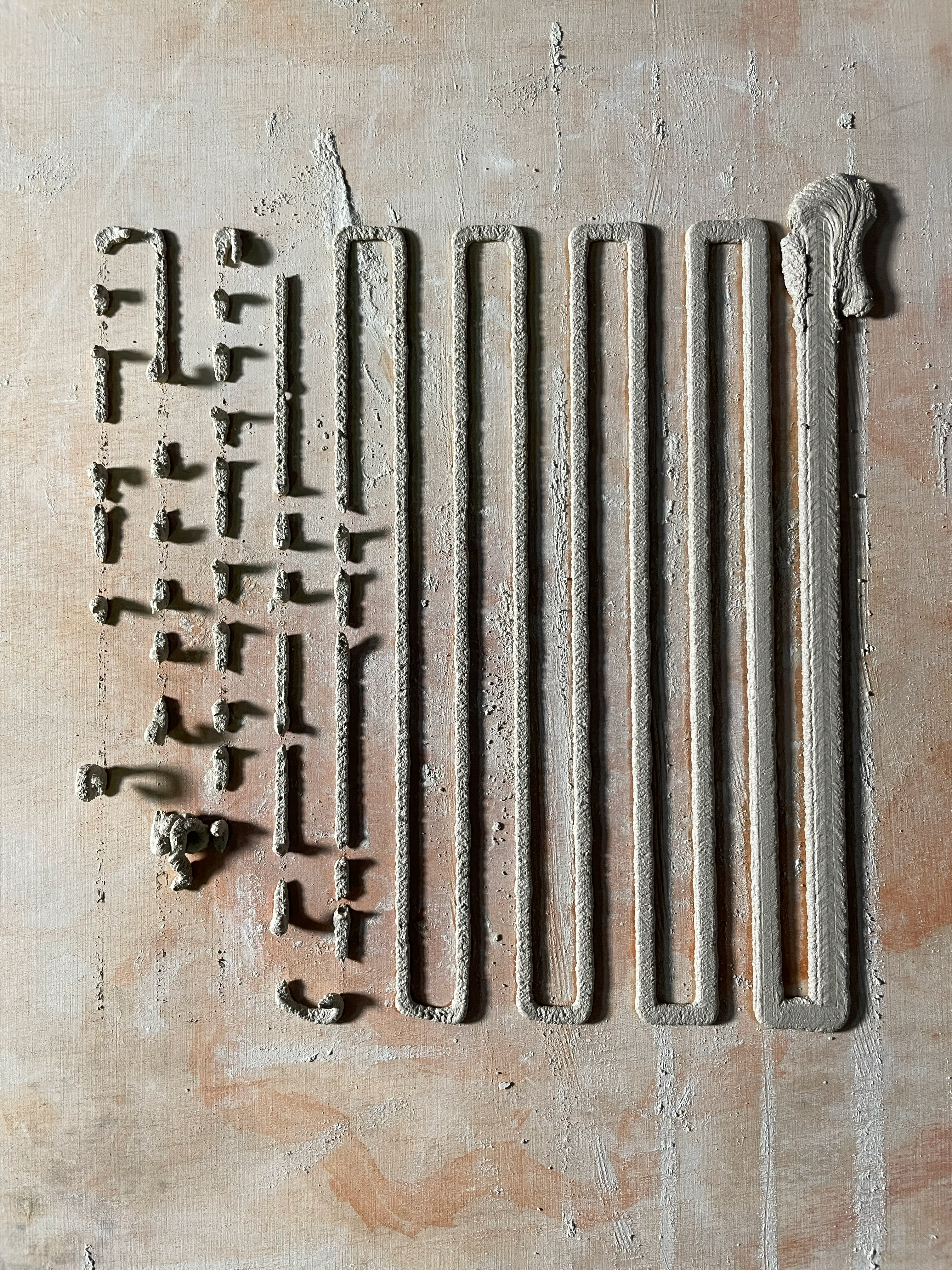
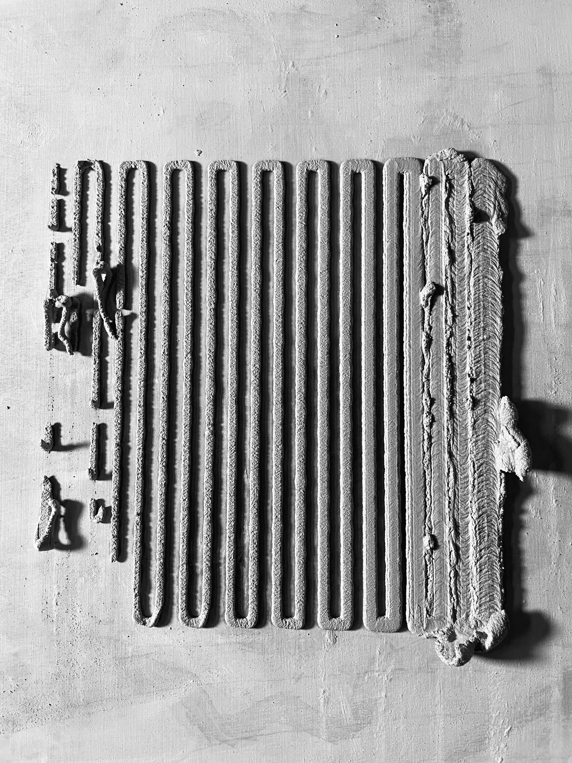
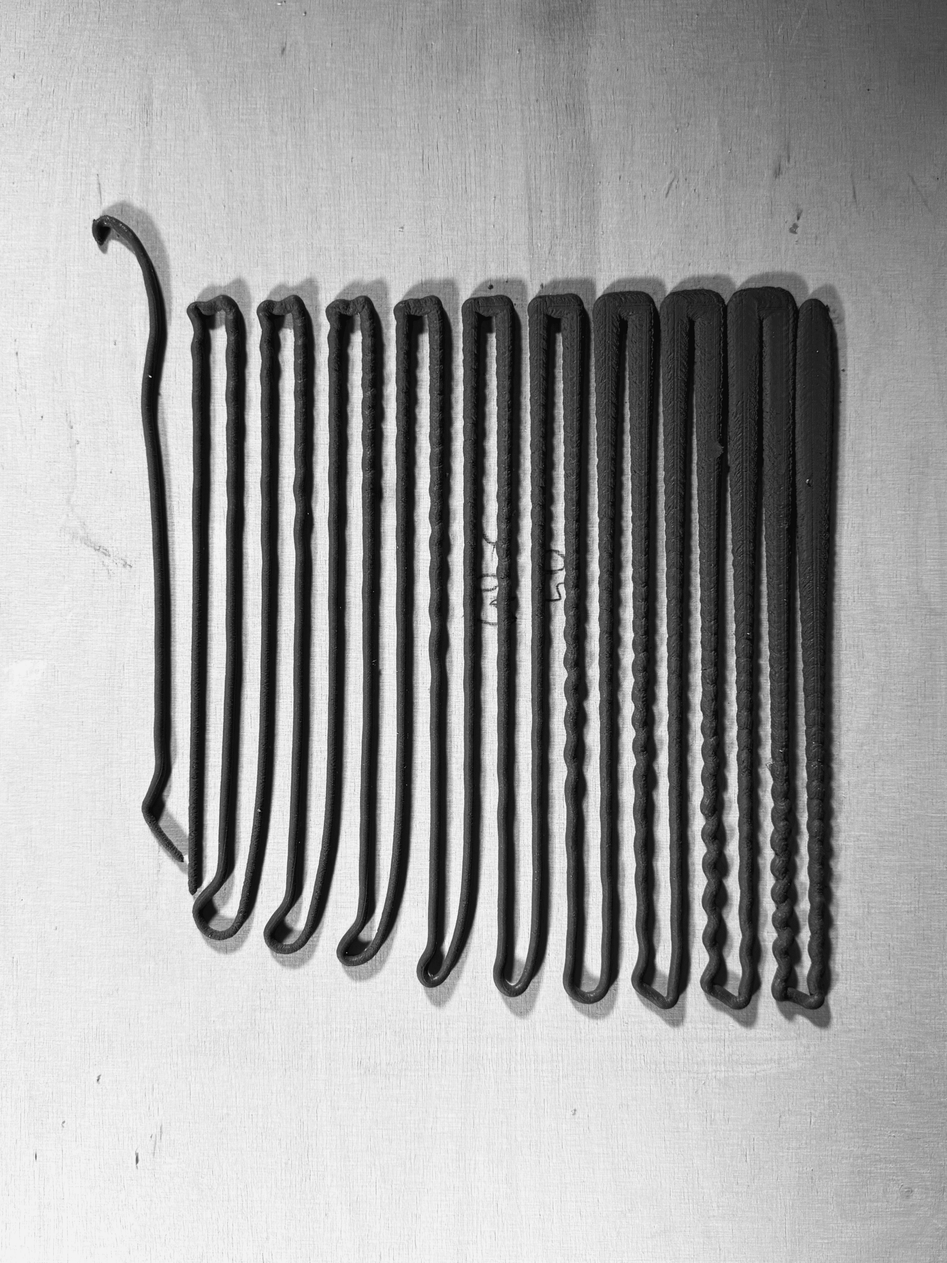
Using the second clay mixture, we conducted a series of tests based on simple linear paths programmed in Grasshopper. These tests explored the relationship between printing height and speed, forming what we referred to as the Anatomy of a Line.
Through this process, we identified a maximum effective printing speed of 15 mm/sec, beyond which material continuity and form stability were compromised.
1st Iteration
Line Spacing: 15 mm
Speed: 3 – 30 seg
![]()
2nd Iteration
Height: 1 – 25 seg
Line Spacing: 10 mm
![]()
3rd Iteration
Height: 2 – 10 mm
Speed: 1 – 25 seg
Spacing: 10 mm
![]()
Line Spacing: 15 mm
Speed: 3 – 30 seg
2nd Iteration
Height: 1 – 25 seg
Line Spacing: 10 mm
3rd Iteration
Height: 2 – 10 mm
Speed: 1 – 25 seg
Spacing: 10 mm
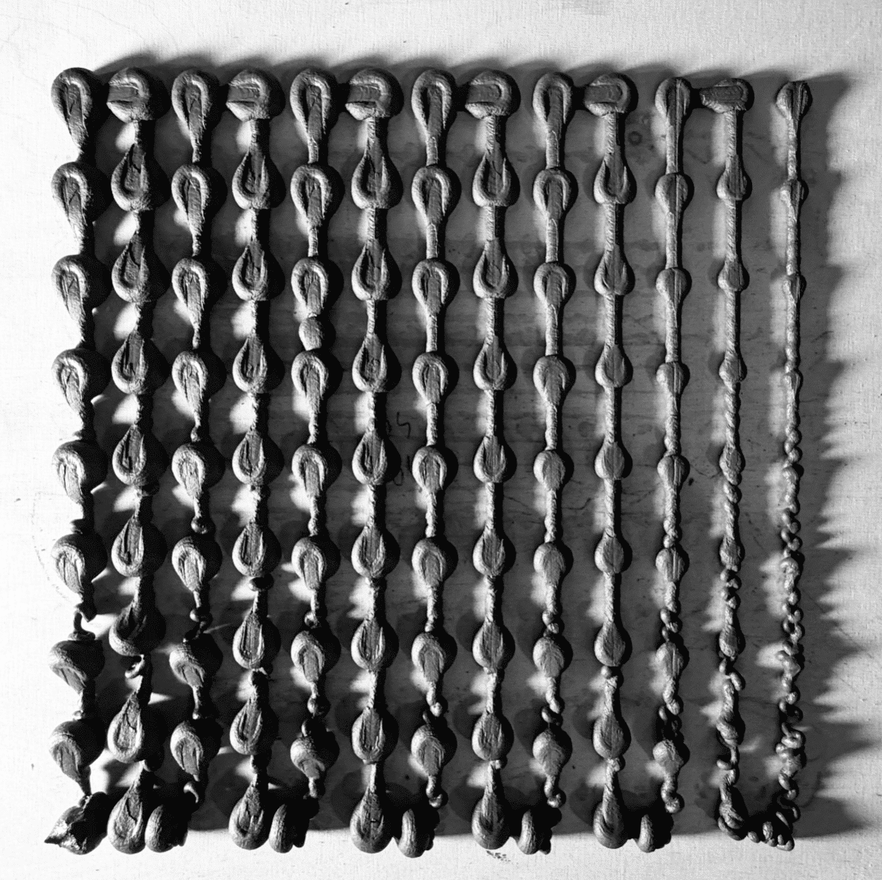
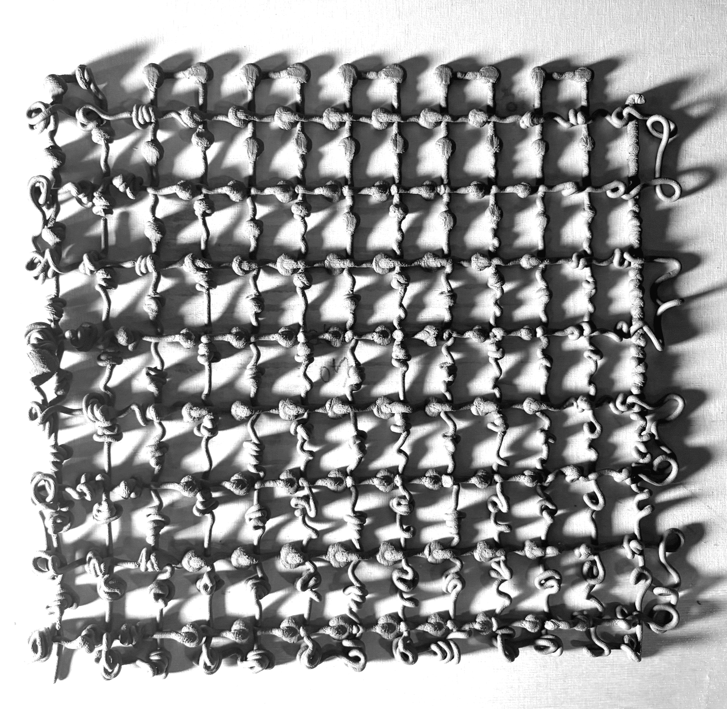
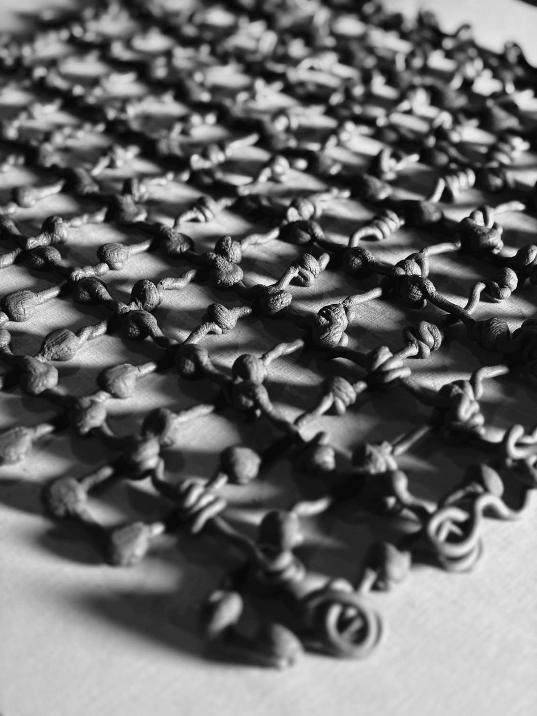
Anatomy of a Line: Height and Waiting Time
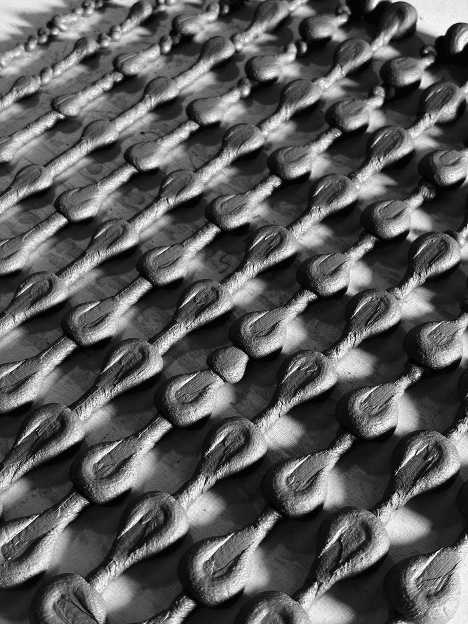
In parallel, we developed a second set of experiments called Anatomy of a Blob. In this case, we focused on two main parameters:
- Printing height
- Waiting time at each plane
The blobs were arranged in two layers forming an orthogonal grid, allowing us to read variations systematically. Beyond generating gradients based on height and waiting time, the blob patterns also visually recorded the directionality of the robotic arm, embedding the machine’s movement logic into the geometry itself.


DIGITAL FABRICATION METHODS - CNC / KUKA / GRASSHOPPER
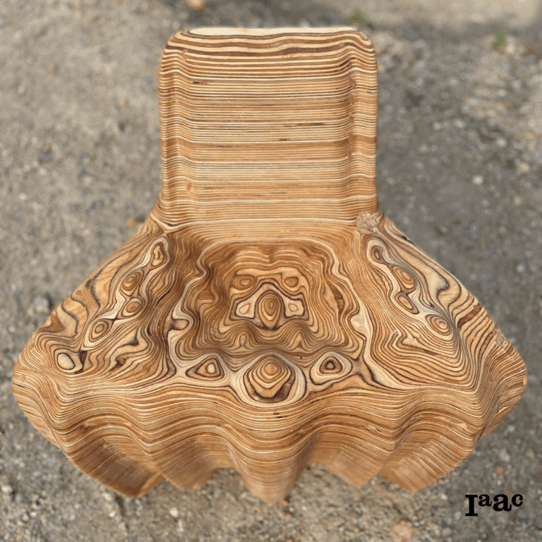
The Massage Chair
The massage chair is an experiment in digital fabrication and hybrid workflows, using computational design, CNC milling, 6-axis robotic milling, and human assembly and finishing, to understand how different subtractive manufacturing processes can be combined to balance speed, precision, and material expression in digital fabrication.
Materials
- 2 sheets plywood
- 54 dowels
- Wood glue
- Linseed oil finish
Tools Used
- Rhino and grasshopper
- CNC
- 6-axis robot
- Manual assembly, sanding, and finish
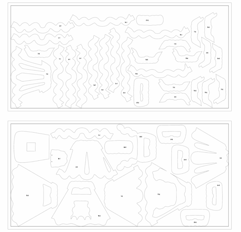
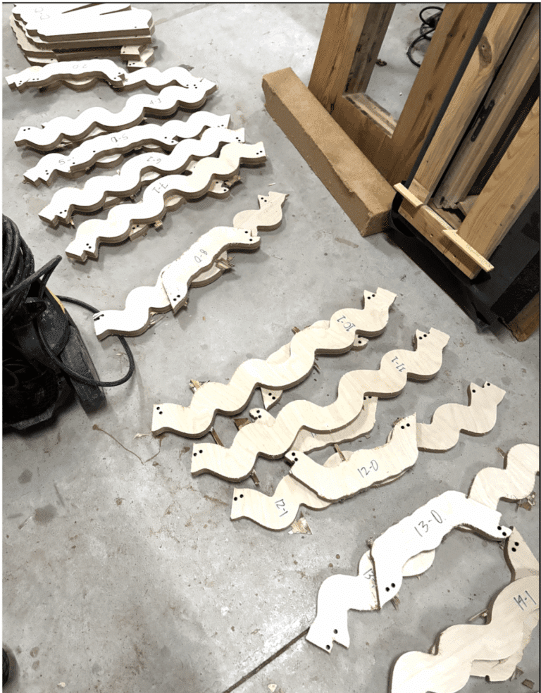
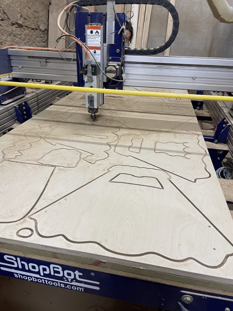
CNC Milling
Script for Nesting
Using a grasshopper script, our 3D design was nested into cuts for CNC milling, optimizing placement on the two plywood sheets to minimize waste, and drilling dowel holes to ensure alignment.


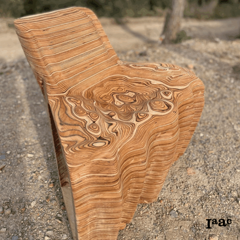
6-axis Robotic Milling
After assembling the chair, we fixed it to the table on an angle for the robotic milling.

Sanding and Finish
Human collaboration was a critical component of creating a polished, sanding topographic surface and cutting or filling the cuts made in error by the robot.
DIGITAL FABRICATION METHODS - ABB ROBOT ARM / CUSTOM MADE ENDEFFECTOR COMBAINED WITH ARDUINO / GRASSHOPPER
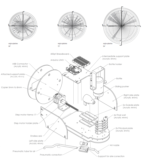
Anatomy of a Machine: SPILL
Team member(s): Xiomara Alcivar, Sam Holcombe, Heleri Koltsin and PRIYAM GULATI RAVINDER
For our second studio task the aim was to further experiment painting with robots; this time extending what paintings could be achieved when a standard brush was replaced by a custom made ‘spilling’ end effector controlled by an Arduino Uno.
This was set through the brief as:
To explore and consider, how a tool might interact with a robot and what movements can be enhanced through robotic intervention. It should also reflect on the unique opportunities and possible limitations that arise when working with robotic arms at this scale.
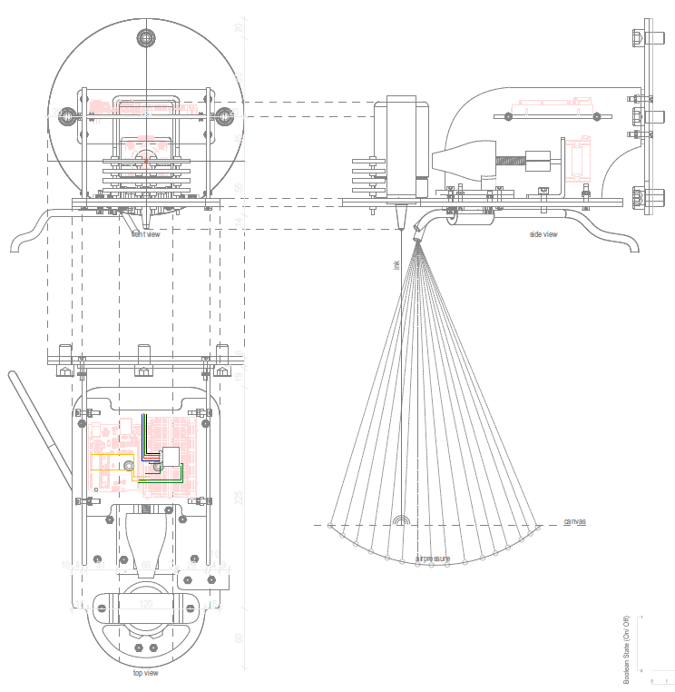
Conceptually, we also wished to challenge the material we were using. Not just asking what the anatomy of the robot was but extending this as question of thinking to the paint material itself. Initially we tried to achieve this mean via mixes. At first this meant mixing soap water and air with the paint to create different bubble patterns.
Although this produced very interesting outcomes, this also began a follow up conversation about precision and control. We thought about how with just air and paint we could also ‘spill’ the material.
Concept at manual stage
- Initially we tried a 28BY-J stepper motor with a ULN2003 driver. This worked but did not provide enough power to squeeze the paint
- We then moved up to a NEMA-17 Stepper with an A498 driver (with attached heat sink). We noticed that squeezing with our fingers still produced a much more controlled spilling pattern. As a result the flat squeezing tool shown on the left was changed out for a convex pusher and wall as shown on the right.
- Syncing the Arduino with the air. In our final trial we realised that even being a tiny step out between the Arduino stepper bounds and solanoid timing meant that over the course of the robot’s movements would no longer work together. Our final challenge was timing the stepper bounds with a delay so that the solanoid would precisely turn on and off before and after the squeezing to ensure we were spilling the paint each time.